Plan of Gates for Lower Lock Upper Side Cut, West Troy --H.C.H. Ellis, n.d.
ink and watercolor on paper, 24 x 35 in.
courtesy of New York State Archives BO292 4:84
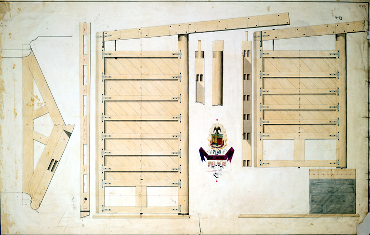
These lock gates were used on a lock that joined the canal with the Hudson River in West
Troy, now Watervliet. When closed, these lock gates met at an angle pointing upstream, and
were braced against a triangular-shaped mitre sill at the bottom of the lock. The drawing on the
left illustrates the mitre sill viewed from above, with one lock gate drawn closed against it.
The large beams at the top are the lock handles, used to open and close the gates. Water was
allowed to pass through the gate via the rectangular valves at the bottom of each gate. Wooden
or metal panels would be placed over the openings and were pulled up to allow water through.
As water pressed against them, the gates would squeeze tighter against each other, making
them more watertight in the center; at the same time, the weight or load of the water would
transfer outward against the solid stone edges of the lock making the gates more watertight at the
edge as well. The gates are attached to a large post called a quoin post, indicated at the right of
each gate. This quoin post was held in place against the stone wall of the lock with a metal strap
at the top (not drawn), and rested on a metal plate at the bottom which pivoted on an iron rod
sunk in wooden timbers resting on the stone foundation. This quoin post fitted tightly against the
stone side of the lock.
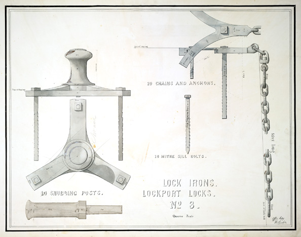
Snubbing posts are placed on top of a lock for boats to tie up to. Mitre sill bolts have teeth
to keep them from pulling out when sunk into rock. Anchors secure chains suspended over the
lock to help crews maneuver or secure boats.
These iron lock accessories come from the Lockport locks. The snubbing posts are drawn
on
the left -- the top snubbing post is shown from the side and from the above. Heavily braced at
the
bottom, it would withstand more pressure than the snubbing post portrayed at the bottom,
although the latter appears to have been the one used, judging by the pencil note on the drawing.